READ Free Dumps For CISCO- 100-105
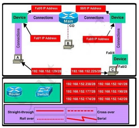
| Question ID 14613 | This topology contains 3 routers and 1 switch. Complete the topology.
Drag the appropriate device icons to the labeled Device
Drag the appropriate connections to the locations labeled Connections.
Drag the appropriate IP addresses to the locations labeled IP address
(Hint: use the given host addresses and Main router information)
To remove a device or connection, drag it away from the topology.
Use information gathered from the Main router to complete the configuration of any
additional routers.
No passwords are required to access the Main router. The config terminal command has
been disabled for the HQ router. The router does not require any configuration.

Configure each additional router with the following:
Configure the interfaces with the correct IP address and enable the interfaces.
Set the password to allow console access to consolepw
Set the password to allow telnet access to telnetpw
Set the password to allow privilege mode access to privpw
Not E: Because routes are not being added to the configurations, you will not be able to
ping through the internetwork.
All devices have cable autosensing capabilities disabled.
All hosts are PCs
|
| Option A | Answer : Specify appropriate devices and drag them on the "Device" boxes For the device at the bottom-right box, we notice that it has 2 interfaces Fa0/2 and Fa0/4; moreover the link connects the PC on the right with the device on the bottom-right is a straight-through link -> it is a switch The question stated that this topology contains 3 routers and 1 switch -> two other devices are routers (Host D and host E will be automatically added after placing two routers. Click on them to access neighboring routers) use a crossover cable use a serial cable use a straight-through cable use a crossover cable - To connect two serial interfaces of 2 routers we use serial cable Router, Host, Server Hub, Switch use straight-through cable use crossover cable For example, we use straight-through cable to connect switch to router, switch to host, hub to host, hub to server... and we use crossover cable to connect switch to switch, switch to hub, router to router, host to host.) From Main router, use show running-config command. From the output we learned that the ip address of Fa0/0 interface of the Main router is 16 (/28 = 255.255.255.240 or 1111 1111.1111 1111.1111 1111.1111 0000) 192.168.152.176 (because 176 = 16 * 11 and 176 < 177) 192.168.152.191 (because 191 = 176 + 16 - 1) 192.168.152.190 and assign it to the Fa0/0 interface the router on the left Use the same method for interface Serial0/0 with an ip address of 192.168.152.161 16 192.168.152.160 (because 160 = 16 * 10 and 160 < 161) 192.168.152.175 (because 176 = 160 + 16 - 1) -> and we choose 192.168.152.174 for Serial0/0 interface of the router on the right Interface Fa0/1 of the router on the left 192.168.152.129/28 16 192.168.152.128 (because 128 = 16 * 8 and 128 < 129) 192.168.152.143 (because 143 = 128 + 16 - 1) -> we choose 192.168.152.142 from the list Interface Fa0/0 of the router on the right 192.168.152.225/28 16 192.168.152.224
|
| Correct Answer | A |
Explanation
| Question ID 14614 | Which component of a routing table entry represents the subnet mask?
|
| Option A | routing protocol code
|
| Option B | prefix
|
| Option C | metric
|
| Option D | network mask
|
| Correct Answer | D |
Explanation Explanation: IP Routing Table Entry TypesAn entry in the IP routing table contains the following information in the order presented: Network ID. The network ID or destination corresponding to the route. The network ID can be class-based, subnet, or supernet network ID, or an IP address for a host route. Network Mask. The mask that is used to match a destination IP address to the network ID. Next Hop. The IP address of the next hop. Interface. An indication of which network interface is used to forward the IP packet. Metric. A number used to indicate the cost of the route so the best route among possible multiple routes to the same destination can be selected. A common use of the metric is to indicate the number of hops (routers crossed) to the network ID. Routing table entries can be used to store the following types of routes: Directly Attached Network IDs. Routes for network IDs that are directly attached. For directly attached networks, the Next Hop field can be blank or contain the IP address of the interface on that network. Remote Network IDs. Routes for network IDs that are not directly attached but are available across other routers. For remote networks, the Next Hop field is the IP address of a local router in between the forwarding node and the remote network. Host Routes. A route to a specific IP address. Host routes allow routing to occur on a per- IP address basis. For host routes, the network ID is the IP address of the specified host and the network mask is 255.255.255.255. Default Route. The default route is designed to be used when a more specific network ID or host route is not found. The default route network ID is 0.0.0.0 with the network mask of 0.0.0.0.