READ Free Dumps For Cisco- 200-125
| Question ID 16097 | On a corporate network, hosts on the same VLAN can communicate with each other, but
they are unable to communicate with hosts on different VLANs. What is needed to allow
communication between the VLANs?
|
| Option A | a router with subinterfaces configured on the physical interface that is connected to the switch
|
| Option B | a router with an IP address on the physical interface connected to the switch
|
| Option C | a switch with an access link that is configured between the switches
|
| Option D | a switch with a trunk link that is configured between the switches
|
| Correct Answer | A |
Explanation Explanation: Different VLANs can't communicate with each other, they can communicate with the help of Layer3 router. Hence, it is needed to connect a router to a switch, then make the sub- interface on the router to connect to the switch, establishing Trunking links to achieve communications of devices which belong to different VLANs. When using VLANs in networks that have multiple interconnected switches, you need to use VLAN trunking between the switches. With VLAN trunking, the switches tag each frame sent between switches so that the receiving switch knows to what VLAN the frame belongs. End user devices connect to switch ports that provide simple connectivity to a single VLAN each. The attached devices are unaware of any VLAN structure. By default, only hosts that are members of the same VLAN can communicate. To change this and allow inter-VLAN communication, you need a router or a layer 3 switch. Here is the example of configuring the router for inter-vlan communication RouterA(config)#int f0/0.1 RouterA(config-subif)#encapsulation ? dot1Q IEEE 802.1Q Virtual LAN RouterA(config-subif)#encapsulation dot1Q or isl VLAN ID RouterA(config-subif)# ip address x.x.x.x y.y.y.y
| Question ID 16098 | Refer to the exhibit.
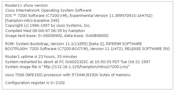
For what two reasons has the router loaded its IOS image from the location that is shown?
(Choose two.)
|
| Option A | Router1 has specific boot system commands that instruct it to load IOS from a TFTP server.
|
| Option B | Router1 is acting as a TFTP server for other routers.
|
| Option C | Router1 cannot locate a valid IOS image in flash memory.
|
| Option D | Router1 defaulted to ROMMON mode and loaded the IOS image from a TFTP server.
|
| Option E | Cisco routers will first attempt to load an image from TFTP for management purposes.
|
| Correct Answer | A,C |
Explanation Explanation: The loading sequence of CISCO IOS is as follows: Booting up the router and locating the Cisco IOS 1. POST (power on self-test) 2. Bootstrap code executed 3. Check Configuration Register value (NVRAM) which can be modified using the config- register command 0 = ROM Monitor mode 1 = ROM IOS 2 - 15 = startup-config in NVRAM 4. Startup-config filE. Check for boot system commands (NVRAM) If boot system commands in startup-config a. Run boot system commands in order they appear in startup-config to locate the IOS b. [If boot system commands fail, use default fallback sequence to locate the IOS (Flash, TFTP, ROM)?] If no boot system commands in startup-config use the default fallback sequence in locating the IOS: a. Flash (sequential) b. TFTP server (netboot) c. ROM (partial IOS) or keep retrying TFTP depending upon router model 5. If IOS is loaded, but there is no startup-config file, the router will use the default fallback sequence for locating the IOS and then it will enter setup mode or the setup dialogue.